To implement the project, we will need:
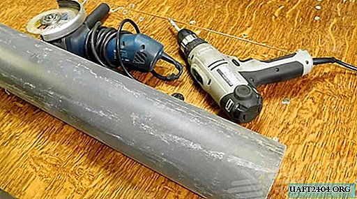
Iron
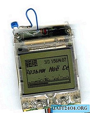
We go into the pantry and look there for a self-defense item with the inscription Ericsson A2618, which has been lying around there since the time of the 45th. (It is desirable that it turns on in order to check the display for functionality).


It is advisable to cut all the tracks that the red line crosses and ring each contact on the body. Only the sixth contact must be called without fail, the rest are not. We emphasize that cut only the tracks. These are thin strips of foil.
We disassemble the LPT cable connector going to the printer and solder it as follows:

Where (left to right):
1. n / a;
2. n / a;
3. n / a;
4. n / a;
5. Blue with a white stripe - Vlcd;
6. Black - Gnd;
7. Orange - Sclk;
8. Gray - Sda;
9. Red - U +;
10. Purple - Reset;
11. n / a;
12. Yellow - U + (backlight);
13. Blue - Gnd (backlight);
14. n / a.
The other end of the cable is soldered to the LPT connector according to the scheme taken from the site www.rifer.narod.ru.

If you use the standard backlight, then a resistor of 1 kOhm value can be excluded from this circuit, because a resistor is already installed on the standard backlight. Even two.
Install the display on the board.
What happened after the work done can be seen below:
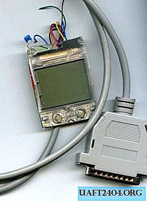
Software
Download and install the LCDHype program. Open and configure, as in the picture.

And copy the text from the Script.txt file into the field.

Queue to configure Winamp.
From the C: Program Files LCDHype stuff winamp folder, copy the files to C: Program Files Winamp Plugins, start the player and follow the illustrated instructions.


Close the settings, do not forget to connect our device to the computer and in LCDHype click "Start". If the circuit is assembled correctly, approximately the following should appear on the display:

We install the device in the case
Only your imagination can help you here.
I installed the display in a case from Microlab. I just installed the module with the display behind the transparent window of the door. I think that I will not describe it, for everyone this process will be individual.


Interested in the article ?! Then spotri links:
//sandiding.tripod.com/Bertys.html
A site for determining the screen output of a large number of phones. That is, you can make your device not only from Ericsson, but also from other models!

