Share
Pin
Tweet
Send
Share
Send
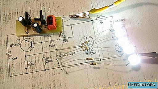
As you know, all modern cars are equipped with direction indicators, which are a light or LED flashing on the left or right side of the body. Sometimes a full-time electromechanical relay fails, and getting a powerful automotive relay is not always so easy. Semiconductor devices come to the rescue - after all, to build such a relay is powerfully just a couple of transistors.
Relay circuit

The circuit is an asymmetric multivibrator; it is connected to the circuit breaker in series with the bulb and the power source. When voltage is applied, the light starts flashing immediately. VT2 in the diagram is a field effect transistor, it is through it that the entire current of the bulb flows. It is preferable to use a transistor with the lowest possible resistance of an open transition. Here fit IRFZ44N, IRF740, IRF630. If a small power LED is used instead of a light bulb, you can use a bipolar transistor, for example, TIP122. Transistor VT1 medium power structure p-n-p, suitable BD140, KT814. Diode D1 can be set 1N4007 or 1N4148. The blinking frequency directly depends on the capacitance of the capacitors and the resistance of the resistors. To increase the frequency, it is necessary to reduce the capacitance of the capacitor C2, and to reduce the frequency, on the contrary, increase its capacity. You can also experiment with the ratings of other elements of the circuit and observe how the duty cycle of the pulses will change.
tranzistornoe-rele-dlja-povorotnikov.zip 97.21 Kb (downloads: 409)

Circuit assembly
The whole circuit is assembled on a miniature printed circuit board measuring 35 x 20 mm, it can be made using the LUT method. Paths after etching must be tinned, then copper will not oxidize.

First of all, resistors and a diode are soldered to the board. After them, everything else is a couple of transistors, electrolytic capacitors and a terminal block. It is important not to confuse the wiring of transistors and the polarity of capacitors, otherwise the circuit will not work. When all the parts are soldered onto the board, it is imperative to wash off the flux residues, check the installation.


Setting and testing turn signal relays
For the test, several powerful LEDs can be connected as a load. We connect the load minus directly to the minus of the power source, and start the plus on the board. If a lamp is used for verification, it can be connected with any polarity. We apply voltage, and the light starts flashing immediately. The flashing frequency can be changed over a wide range, which is why many other applications can be found in this circuit besides using turn signals as relays. For example, with its help you can make a rear flashing light for a bicycle, you just need to increase the frequency of flashes by reducing the capacitance of the capacitor. The circuit can switch a large power - up to several hundred watts, if you use a field effect transistor designed for the corresponding current. With a power of more than 100 watts, it is advisable to install the transistor on a small radiator, otherwise it may heat up during long-term operation. Such a circuit, unlike a traditional electromechanical relay, does not have moving parts, therefore it is much more durable if used with a part of proper quality. If necessary, a fuse is also connected to the circuit in series with the load, indicated on the diagram as FU1. Successful assembly.


The video demonstrates the operation of this circuit, several LEDs with resistors are used as the load.
Share
Pin
Tweet
Send
Share
Send


